The VendorN Ltd OneDDI product (OneDDI) is a centralised software application which hosts several modules.
The ReDNS module allows a business to pre-define all DNS records for critical services. Service owners can be permitted to control service DNS records and perform on-demand extensive health-checks to identify configuration issues.
The IPMeye module provides centralised remote power management and console access using the IPMI protocol. It enforces access control and audits all user actions.
The SerialEyes module provides centralised remote physical serial port access via non-dedicated hardware. A SerialEyes bootable USB drive transforms a laptop into an on-demand secure physical serial port gateway using existing addressing and connectivity.
This document details all pages and features provided by the OneDDI Web User Interface (WebUI).
This document is aimed at all users.
The OneDDI WebUI is provided by the OneDDI server. By default, the application is available using HTTPS and the TCP port 443.
This may have changed following initial installation and the OneDDI product administrator should be consulted to confirm which port is being used.
Once confirmed the WebUI can be accessed using the following URL:
https://<ip-address-or-hostname>
Once the WebUI has initially loaded the Login page will be displayed.
NOTE If replication has been configured by an administrator, and the instance being connected to is not an active peer, the user will be redirected to the active peer as per the replication configuration.
Above the login form on the Login page a configurable Message of the Day (MOTD) will be displayed.
Below the MOTD the login form will be displayed, where a username and password can be entered to login.
A product administrator will confirm the credentials to use when accessing the
WebUI. Once these have been entered, and authentication was successful, the
ReDNS page will be displayed by default if a license is installed for the
redns module, otherwise the IPMeye page will be displayed by default.
NOTE If a specific WebUI page has been requested that page will be displayed following successful login.
After successful login to the WebUI the ReDNS / Services page will be
displayed by default if a license is installed for the redns module,
otherwise the IPMeye page will be displayed by default.
At the top of each page a menu bar will be displayed. This will have links to the main features of the application, and menu containing product help and the production administration links.
The menu bar is mostly self-explanatory, the product is generally split into the following areas:
Displayed furthest to the right in the menu bar will be a user action menu containing links for Change my password, Access user guide and Logout. Refer to the Change My Password section for details on the Change my password dialog.
Below the menu bar the page content area is displayed, this will be different for each page. The remaining sections in this document detail all of the pages and features available in the WebUI.
The Change my password dialog can be accessed by selecting the Change my password link displayed in the user action menu displayed in the top menu bar.
Each user can change their own password using the Change my password dialog once authenticated.
The following fields are displayed in this page:
OneDDI is configured with a password complexity policy. A description of the currently configured policy will be displayed. The following is the default policy description:
Password must be at least 8 characters and contain at least 1 upper case
letter, 1 lower case letter, 1 number and 1 of '!@#$%^&*'
Upon clicking the SAVE button the password will be changed immediately.
Services are viewed and managed under the ReDNS / Services page by clicking the ReDNS link displayed in the top menu bar and clicking the Services link.
The ReDNS / Services page will display a table of all defined services.
The following columns are displayed in the table for each service:
www.vendorn.comInternal Infoblox GridA search control is displayed to the top right of the table. Values in the search field will be matched against a services Service FQDN, DNS view, description or active records. Additionally, services can be filtered by service group using the service group dropdown in the header of the service group column in the table.
Paging controls are displayed to the bottom right of the table. These can be used to page through the list of services, and to control how many are displayed in a single page.
The button ADD A SERVICE will be displayed to the top left of the table. If the currently authenticated user has NOT been assigned permission to manage services, this button will be disabled. Upon clicking this button, the Add a service dialog will be displayed. See the ReDNS / Services / Add a Service section for details on this dialog and adding services.
The link EXPORT TO CSV will be displayed to the top of the left of the table. Upon clicking this link all services will be exported to a CSV file and downloaded. See the ReDNS / Services / Export to CSV section for details on exporting services.
The link VIEW SERVICE will be displayed to the right of each service. Upon clicking this link the View service page will be displayed for the service. See the ReDNS / Services / View service section for details on this page and viewing services.
Upon hovering over a row in the table an edit service, delete service and edit service permissions button will be displayed to the right. If the currently authenticated user has NOT been assigned permission to manage services the edit service and delete service buttons will be disabled, and the edit service permissions button is replaced with a view service permissions button.
Upon clicking the edit service button, the Edit service dialog will be displayed. See the ReDNS / Services / Edit a Service section for details on this dialog and editing a service.
Upon clicking the delete service button the Delete service dialog will be displayed. See the ReDNS / Services / Delete a Service section for details on this dialog and deleting a service.
Upon clicking the view or edit service permissions button the Edit service permissions or View service permissions dialog will be displayed depending on whether a user has been assigned permissions to manage services. See the ReDNS / Services / Services Permissions section for details on this dialog and service permissions.
Services are added using the Add a service dialog. This can be accessed by clicking the ADD A SERVICE button displayed in the ReDNS / Services page. If the currently authenticated user NOT been assigned permission to manage services, this button will be disabled.
This dialog contains the following inputs:
defaultwww.vendorn.comOnce all required attributes have been specified the ADD button will be enabled, and once clicked the service will be added.
Service are imported using the Import service records dialog. This can be accessed by clicking the IMPORT SERVICE RECORDS button displayed in the ReDNS / Service Records page. If the currently authenticated user NOT been assigned permission to manage services this button will be disabled.
During import, when a service record is added, if the service specified for the service record does not exist it will be automatically created before the service record is added. This means that a service record must be imported to be able to import a service.
See the ReDNS / Service Records / Import Service Records section for more details on this dialog and importing service records.
Services are exported to CSV using the EXPORT TO CSV link displayed in the ReDNS / Services page. Upon clicking this link all services will be exported to a CSV file and downloaded, with the resulting CSV file having the following fields:
svc1.vendorn.com.Internal Grid.defaultPublic serviceService permissions are viewed and edited using the View service permissions and Edit service permissions dialogs. These can be accessed by clicking the view service permissions or edit service permissions buttons displayed to the right when hovering over a service in the ReDNS / Service page, or displayed to the right of a services Service FQDN at the top of the View service page. If the currently authenticated user has NOT been assigned permission to manage services the view service permissions button will be accessible otherwise the edit service permissions button will be accessible.
The View service permissions dialog displays all the groups which are permitted to swap the active service records for as service.
Note that this permission does not allow management of the service. A user
must be associated with a group which has the manage-services permission
assigned to be able to manage services. Permissions assigned at the service
level are to swap the active service records of a service only, which includes
changing service TTL’s.
The Edit service permissions dialog also displays all the groups which are permitted to swap the active service records for as service. Additionally, an EDIT SELECTED GROUPS button is displayed to permit selecting and deselecting which groups should be assigned the permission, after which the SAVE button can be used to save the selected permissions.
Detailed information about a service and its service record state can be accessed by clicking the VIEW SERVICE link displayed to the right of a service under the ReDNS / Services and ReDNS / Service Records pages.
The View service page is divided into multiple sections.
At the top of the View service page the services Service FQDN, Infoblox connector, Infoblox DNS view, service group and description are displayed. Additionally, an edit service, delete service and edit service permissions buttons will be displayed to the right. If the currently authenticated user has NOT been assigned permission to manage services the edit service and delete service buttons will be disabled, and the view service permissions button will be displayed in place of the edit service permissions button.
The SERVICE STATUS section displays how many of the services configured
service records are active, and when the service was last actioned - i.e. the
last time service records were swapped or service TTL’s changed. A SWAP
ACTIVE SERVICE RECORDS button is displayed to the bottom of the panel. If the
currently authenticated user has NOT been assigned permission to manage
services, or is not associated with a group that is specified in the services
permissions, this button will be disabled. Upon clicking this button, the
Swap active service records dialog will be displayed. See the
ReDNS / Services / Swap Active Service Records section for details on this
dialog and swapping the active service records for a service. A
VIEW SWAP HISTORY link will also be displayed to the bottom of the panel,
when clicked the Swap history page will be displayed for the service. See
the ReDNS / Services / Swap History section for details on this page. If no
swap has occurred yet, then No data available will be displayed in the panel.
The BCP JOBS section displays a list of BCP jobs which have the service configured. Displayed to the right of each BCP job is a VIEW BCP JOB link, and when clicked the View BCP job page will be displayed for a BCP job. See the View BCP job page for details on this page.
The SERVICE RECORDS section displays a table containing the service records configured for the service and whether they are currently active in the underlying platform.
The following columns are displayed in the table for each service:
a-record or cname-record1 hour, hovering
over the field displays the number TTL in seconds, if the service record is
configured not to override the DNS zone default TTL this will be the string
Use DNS zone defaultWhen a service record is active the service FQDN will be displayed to the left of the service record in the table in green. This is to indicate the service FQDN currently resolves to the service records specified target.
A search control is displayed to the top right of the table. Values in the search field will be matched against a service records record type or target.
Paging controls are displayed to the bottom right of the table. These can be used to page through the list of service records, and to control how many are displayed in a single page.
The button ADD A SERVICE RECORD will be displayed to the top left of the table. If the currently authenticated user has NOT been assigned permission to manage services this button will be disabled. Upon clicking this button, the Add a service record dialog will be displayed. See the ReDNS / Services / Add a Service Record section for details on this dialog and adding service records.
The button CHECK SERVICE HEALTH will also be displayed to the top left of the table. Upon clicking this button, the Check service health dialog will be displayed. See the ReDNS / Services / Check Service Health section for details on this dialog and performing service health checks.
The button CHANGE SERVICE TTL’S will also be displayed to the top left of the table. If the currently authenticated user has NOT been assigned permission to manage services, or is not associated with a group that is specified in the services permissions, this button will be disabled. Upon clicking this button, the Change service TTL’s dialog will be displayed. See the ReDNS / Services / Change Service TTL’s section for details on this dialog and changing service TTL’s.
Upon hovering over a row in the table an edit service record and delete service record button will be displayed to the right. If the currently authenticated user has NOT been assigned permission to manage services these buttons will be disabled.
Upon clicking the edit service record button, the Edit service record dialog will be displayed. See the ReDNS / Services / Edit a Service Record section for details on this dialog and editing a service record.
Upon clicking the delete service record button the Delete service record dialog will be displayed. See the ReDNS / Services / Delete a Service Record section for details on this dialog and deleting a service record.
Services records are added using the Add a service record dialog. This can be accessed by clicking the ADD A SERVICE RECORD button displayed in the ReDNS / Services / View service page for a service. If the currently authenticated user has NOT been assigned permission to manage services, this button will be disabled.
This dialog contains several tabs. The RECORD tab contains the following inputs:
a-record - Use a DNS A resource record in the underlying platform to
manage the service recordcname-record - Use a DNS CNAME resource record in the underlying
platform to manage the service recordhost-alias - Use an alias on a host object in the underlying platform to
manage the service recordhost-object - Use a host object in the underlying platform to manage the
service recorda-record the IP address must be specified, when the record is active the
Service FQDN will resolve to the value specifiedcname-record a Fully Qualified Domain Name must be specified, when the
service record is active the Service FQDN will resolve to the value
specifiedhost-alias the Fully Qualified Domain Name of the host object must be
specified, when the service record is active the Service FQDN will
resolve to the value specifiedhost-object the IP address for a host object must be specified, if a
host object has multiple IP addresses configured in the underlying platform
only one of the configured addresses should be specified, when the record is
active the Service FQDN will resolve to the value specifiedCreate the record when it is active and
delete when in-active from the underlying platform, or to Rename the
record when in-active to a specified in-active FQDN in the underlying
platformRename the
record when in-active to a specified in-active FQDN this field will
be enabled and required and must contain the Fully Qualified Domain Name the
service record will be renamed to in the underlying platform when it is not
activeThe TTL tab contains the following inputs:
0 to 2147483647 can be specified, this
field will be disabled unless the Select to override the DNS zone default
TTL field is selectedOnce all required attributes have been specified the ADD button will be enabled, and once clicked the service record will be added.
Service records are edited using the Edit service record dialog. This can be accessed by clicking the edit service record button displayed to the right when hovering over a service record in the ReDNS / Services / View service page for a service. If the currently authenticated user NOT been assigned permission to manage services, this button will be disabled.
This dialog contains several tabs. The RECORD tab contains the following inputs:
a-record - Use a DNS A resource record in the underlying platform to
manage the service recordcname-record - Use a DNS CNAME resource record in the underlying
platform to manage the service recordhost-alias - Use an alias on a host object in the underlying platform to
manage the service recordhost-object - Use a host object in the underlying platform to manage the
service recorda-record the IP address must be specified, when the record is active the
Service FQDN will resolve to the value specifiedcname-record a Fully Qualified Domain Name must be specified, when the
service record is active the Service FQDN will resolve to the value
specifiedhost-alias the Fully Qualified Domain Name of the host object must be
specified, when the service record is active the Service FQDN will
resolve to the value specifiedhost-object the IP address for a host object must be specified, if a
host object has multiple IP addresses configured in the underlying platform
only one of the configured addresses should be specified, when the record is
active the Service FQDN will resolve to the value specifiedCreate the record when it is active and
delete when in-active from the underlying platform, or to Rename the
record when in-active to a specified in-active FQDN in the underlying
platformRename the
record when in-active to a specified in-active FQDN this field will
be enabled and required and must contain the Fully Qualified Domain Name the
service record will be renamed to in the underlying platform when it is not
activeThe TTL tab contains the following inputs:
0 to 2147483647 can be specified, this
field will be disabled unless the Select to override the DNS zone default
TTL field is selectedClick the SAVE button to save changes to the service record.
NOTE This is a destructive operation which cannot be undone.
Service records are deleted using the Delete service record dialog. This can be accessed by clicking the delete service record button displayed to the right when hovering over a service record in the ReDNS / Services / View service page for a service. If the currently authenticated user NOT been assigned permission to manage services, this button will be disabled.
The delete dialog prompts whether the service record should be deleted.
Click the DELETE button to confirm the service record should be deleted, after which the service record will be deleted.
The health of a service and its configured service records can be checked using the Check service health dialog. This can be accessed by clicking the CHECK SERVICE HEALTH button displayed in the ReDNS / Services / View service page for a service.
During a service health check the underlying platform will be queried to understand the current state of the service and its service records. The service health check will attempt to identify issues which would prevent the successful swap of any of the configured service records. The service health check will also attempt to identify service records not configured in OneDDI.
Click the START SERVICE HEALTH CHECK button to perform the health check.
A progress bar is displayed and updated as the health check progresses. As issues are identified they will be displayed. Once the health check is complete, if no errors were found the progress bar will be coloured green and indicate that no issues were found. Otherwise the progress bar will be coloured red and indicate at least one issue was found.
For each issue found either an amber triangle or a red warning circle is displayed. Amber should be addressed, but they would not prevent the service from being successfully swapped. Red items are likely to prevent a service from being swapped successfully, and should be addressed.
Each issue identifies an issue with either one of the configured service records for a service, or the services Service FQDN itself. The exact item is displayed along with details of the issue. The following is an example issue:
In the above error an issue was identified with the service record which is
configured with the record type of a-record and the target IP address of
1.1.1.1.. The service record is marked as active in OneDDI, but when
consulting the underlying Infoblox platform no A record could be found for the
Service FQDN of svc1.vendorn.com which resolved to 1.1.1.1.
This issue would prevent a successful swap of the service and would have to be addressed.
The TTL’s for all service records for a service can be changed using the Change service TTL’s dialog. This can be accessed by clicking the CHANGE SERVICE TTL’S button displayed in the SERVICE RECORDS panel in the ReDNS / Services / View service page for a service. If the currently authenticated user has NOT been assigned permission to manage services, or is not associated with a group that is specified in the services permissions, this button will be disabled. Either permission is required to change service TTL’s.
The Change service TTL’s dialog displays a three step wizard which guides a user through specifying new TTL configuration, reviewing the changes which will be made, and then executing each change while displaying progress.
Upon entering the wizard step 1, the New TTL configuration page, is displayed.
This step can be used to specify the new TTL configuration. Two radio button
options are presented, one must be selected. The first Configure all service
records to use the following TTL allows a TTL to be specified in seconds with
several pre-sets provided for quick selection. The second Remove the
existing TTL configuration and use the DNS zone default TTL results in the
existing TTL configuration being removed and the service records inheriting the
DNS zone defaults TTL.
Once the new TTL configuration has been specified the NEXT button can be clicked to move on to step 2, the Review actions page. This page presents what changes will be made to the underlying platform to change service TTL’s. A table is displayed consisting of one row per service record, with the following columns:
Record type - The record type for the service recordTarget - A Fully Qualified Domain Name or IP address depending on what
record type the service record is configured forNew TTL - The TTL which the service record will be reconfigured to use,
e.g. 1 hour, hovering over this field will result in a tooltip being
displayed which shows the TTL in seconds, if the service record is
configured to use the DNS zone default TTL this will be the string
Use DNS zone defaultOnce the actions have been reviewed, the select field Select to continue if an error occurs processing an action can be selected to indicate if an error occurs processing a service record it should not prevent the TTL changes from running to completion, an attempt will be made to change the TTL’s of all service records in this case. Otherwise, if not selected, the TTL change will stop at the first error.
Once a comment has been entered in the required Comment field the CHANGE NOW button can be clicked after which step 3, the Process actions page will be displayed and the TTL change will start.
During the TTL change each action is processed and a progress bar updated. Once complete, if the TTL change was successful the progress bar will turn green and indicate the TTL change completed successfully. Otherwise the progress bar will turn red and indicate at least one error occurred.
A results table will also be displayed containing all the service records actioned and the outcome. If an error occurred actioning a service record the error will be displayed in the results table alongside the corresponding service record.
Once the TTL change is complete click the CLOSE button to close the dialog.
The active service records for a service can be swapped using the Swap active service records dialog. This can be accessed by clicking the SWAP ACTIVE SERVICE RECORDS button displayed in the SERVICE STATUS panel in the ReDNS / Services / View service page for a service. If the currently authenticated user has NOT been assigned permission to manage services, or is not associated with a group that is specified in the services permissions, this button will be disabled.
The Swap active service records dialog displays a three step wizard which guides a user through selecting which service records should be active, reviewing the changes which will be made, and then executing each change while displaying progress.
Upon entering the wizard step 1, the Edit service records page, is displayed. This step can be used to select which service records should be active following the swap. The step is prepopulated with the service records currently active for the service. An EDIT SELECTED SERVICE RECORDS button is displayed to the bottom, which can be used to add and remove selected service records from the list.
Once the require service records have been selected the NEXT button can be clicked to move on to step 2, the Review actions page. This page presents what changes will be made to the underlying platform during the swap. A table is displayed with the following columns:
Action - Either activate indicating the service record is added or
renamed so that the Service FQDN resolves to the service record
following the swap, deactivate indicating the service record is deleted or
renamed so that the Service FQDN no longer resolves to the service
record following the swap, or unchanged indicating the service is already
active and does not require activatingRecord type - The record type for the service recordTarget - A Fully Qualified Domain Name or IP address depending on what
record type the service record is configured forSwap action - A summary of what record will be added/renamed during the
swap of the service recordOnce the actions have been reviewed, the select field Select to continue if an error occurs processing an action can be selected to indicate if an error occurs processing a service record it should not prevent the swap from running to completion, attempting to swap all records. Otherwise, if not selected, the swap will stop at the first error.
Once a comment has been entered in the required Comment field the SWAP NOW button can be clicked after which step 3, the Process actions page will be displayed and the swap will start.
During the swap each action is processed and a progress bar updated. Once complete, if the swap was successful the progress bar will turn green and indicate the swap completed successfully. Otherwise the progress bar will turn red and indicate at least one error occurred.
A results table will also be displayed containing all the service records actioned and the outcome. If an error occurred actioning a service record the error will be displayed in the results table alongside the corresponding service record.
Once the swap is complete click the CLOSE button to close the dialog.
The swap history for a service can be viewed under the Swap history page by clicking the VIEW SWAP HISTORY link displayed in the SERVICE STATUS panel in the ReDNS / Services / View service page for a service.
Each time a service record is activated or deactivated a swap audit event is recorded and associated with the service. In addition when service TTL’s are changed an audit event is also recorded. The Swap history page displays a table of the audit events for a specific service.
The following columns are displayed in the table for each audit event:
2 hours ago,
hovering over this field will result in a tooltip being displayed which
shows the date and time in ISO formatactivate, deactivate or change-ttl depending on
what the audit event is for1 hour, hovering over this field will result in a tooltip
being displayed which shows the TTL in seconds, if the service record is
configured not to override the DNS zone default TTL at the time the service
record was swapped this will be the string Use DNS zone defaultCreate marketplace.internal -> 1.1.1.1 or
Change TTL for marketplace.internal -> 2.2.2.2A search control is displayed to the top right of the table. Values in the search field will be matched against all displayed fields excluding the timestamp field.
Paging controls are displayed to the bottom right of the table. These can be used to page through the list of swap audit events, and to control how many are displayed in a single page.
Services are edited using the Edit service dialog. This can be accessed by clicking the edit service button displayed to the right when hovering over a service in the ReDNS / Services page, or displayed to the right of a service’s FQDN at the top of the ReDNS / Services / View service page. If the currently authenticated user NOT been assigned permission to manage services, this button will be disabled.
This dialog contains the following inputs:
defaultwww.vendorn.comClick the SAVE button to save changes to the service.
NOTE This is a destructive operation which cannot be undone.
Services are deleted using the Delete service dialog. This can be accessed by clicking the delete service button displayed to the right when hovering over a service in the ReDNS / Services page, or displayed to the right of a service’s FQDN at the top of the ReDNS / Services / View service page. If the currently authenticated user NOT been assigned permission to manage services, this button will be disabled.
The delete dialog prompts whether the service should be deleted.
Click the DELETE button to confirm the service should be deleted, after which the service will be deleted.
Services records are viewed and managed under the ReDNS / Services / View service page by clicking the VIEW SERVICE link displayed to the right of a service in the ReDNS / Services page, or under the ReDNS / Service Records which can be accessed by clicking the ReDNS link in the top menu bar and clicking the Services records link.
The ReDNS / Service Records page will display a table of all defined services.
The following columns are displayed in the table for each service record:
www.vendorn.com,
for the service the service record relates toInternal Infoblox GridA search control is displayed to the top right of the table. Values in the search field will be matched against a services Service FQDN, DNS view, record type or target. Additionally, services records can be filtered by service group using the service group dropdown in the header of the service group column in the table.
Paging controls are displayed to the bottom right of the table. These can be used to page through the list of services, and to control how many are displayed in a single page.
The button IMPORT SERVICE RECORDS will be displayed to the top of the left of the table. If the currently authenticated user has NOT been assigned permission to manage services this button will be disabled. Upon clicking this button, the Import service records dialog will be displayed. See the ReDNS / Service records / Import Service Records section for details on this dialog and importing service records.
The link EXPORT TO CSV will be displayed to the top of the left of the table. Upon clicking this link, all service records will be exported to a CSV file and downloaded. See the ReDNS / Services Records / Export to CSV section for details on exporting service records.
The link VIEW SERVICE will be displayed to the right of each service record. Upon clicking this link, the View service page will be displayed for the service the service record relates to. See the ReDNS / Services / View service section for details on this page and viewing services.
Upon hovering over a row in the table an edit service record, and delete service record button will be displayed to the right. If the currently authenticated user has NOT been assigned permission to manage services, the edit service record and delete service record buttons will be disabled.
Upon clicking the edit service record button, the Edit service record dialog will be displayed. See the ReDNS / Services / Edit a Service Record section for details on this dialog and editing a service record.
Upon clicking the delete service record button, the Delete service record dialog will be displayed. See the ReDNS / Services / Delete a Service Record section for details on this dialog and deleting a service record.
Service records are imported using the Import service records dialog. This can be accessed by clicking the IMPORT SERVICE RECORDS button displayed in the ReDNS / Service Records page, which can be accessed by clicking the ReDNS link in the top menu bar and clicking the Services records link. If the currently authenticated user NOT been assigned permission to manage services, this button will be disabled.
Services are also imported using the Import service records dialog. During import, when a service record is added, if the service specified for the service record does not exist it will be automatically created before the service record is added. This means that a service record must be imported to be able to import a service.
In this dialog a CSV import file must be specified which contains the service records to be imported. The CSV import file should define one service record per line using the following fields:
FQDN,Connector,DNS view,Service group,Description,Record type,Target,Override zone TTL,TTL,Swap action,In-active FQDN,Is active
The FQDN, Connector, Service group, DNS view and Description fields
identify the corresponding service the service record is to be associated with.
If the service already exists, the Service group and Description fields can
be left blank. If the service does not yet exist it will be automatically
created during import, therefore the first instance of the service in the CSV
import file should have a value in the Service group and Description fields
to set the service group and description for the automatically created service.
The remaining fields are required as follows:
a-record - Use a DNS A resource record in the underlying platform to
manage the service recordcname-record - Use a DNS CNAME resource record in the underlying
platform to manage the service recordhost-alias - Use an alias on a host object in the underlying platform to
manage the service recordhost-object - Use a host object in the underlying platform to manage the
service recorda-record the IP address
must be specified, if the Record type was specified as cname-record a
Fully Qualified Domain Name must be specified, if the Record type was
specified as host-alias the Fully Qualified Domain Name of the host object
must be specified, if the Record type was specified as host-object the
IP address for a host object must be specified, if a host object has
multiple IP addresses configured in the underlying platform only one of the
configured addresses should be specifiedyes to use the value specified in the TTL
field for the DNS service records TTL, or no to use the DNS zones default
TTLyes then this field is
ignored, otherwise specify the TTL in seconds for the DNS service recorddelete the service record from the
underling platform when it is in-active (later adding again when it is made
active), or whether to retain the service record but rename it to the
specified In-active FQDN by specifying rename for this fielddelete this field will
be ignored, otherwise the field is required and must contain the Fully
Qualified Domain Name the service record will be renamed to in the
underlying platform when it is not activeyes if the service is in an active state in the
underlying platform, i.e. the service FQDN currently resolves to the
target specified and is using the specified Record typeIf the CSV import file contains a header row as its first row, ensure the Select to skip the first row in the CSV import file if it contains headers field is selected to ignore the first row.
An example CSV import file can also be downloaded using the DOWNLOAD EXAMPLE CSV IMPORT FILE link which can be used as a starting point for a CSV import.
Once the CSV import file has been specified the VERIFY button can be clicked. A check will be performed to ensure an existing service record for the specified record type and target does not already exist. If an existing service record is found an error will be displayed.
Once successfully verified the IMPORT button can be clicked. Once clicked all service records will be added along with any services which are to be automatically created.
Service records are exported to CSV using the EXPORT TO CSV link displayed in the ReDNS / Service Records page. Upon clicking this link all service records for all services will be exported to a CSV file and downloaded, with the resulting CSV file having the following fields:
svc1.vendorn.com.Internal Grid.defaultNetwork AppsPublic servicea-record,
cname-record, host-alias or host-objectyes to indicate the TTL field contains the
TTL used for the service record, or no to indicate the DNS zone default
TTL will be used for the service recordyes this field contains the
TTL used for the service record, otherwise this field contains the value 0delete to indicate service records are added and
deleted when they are made active and in-active, or rename to indicate
service records are renamed from and to the Fully Qualified Domain Name
specified in the In-active FQDN field when they are made active and
in-activerename this field
contains the Fully Qualified Domain Name used by the service record when it
is in-activeyes to indicate the services Fully Qualified Domain
Name currently resolves to the service record, otherwise this field will be
noNote when exporting service records, when a service has more than one service record the service will appear multiple times, once for each line - which will contain a service record.
BCP jobs are viewed and managed under the ReDNS / BCP Jobs page by clicking the ReDNS link displayed in the top menu bar and clicking the BCP jobs link.
The ReDNS / BCP Jobs page will display a table of all defined BCP jobs.
The following columns are displayed in the table for each BCP job:
A search control is displayed to the top right of the table. Values in the search field will be matched against the name and service groups fields.
Paging controls are displayed to the bottom right of the table. These can be used to page through the list of BCP jobs, and to control how many are displayed in a single page.
The button ADD A BCP JOB will be displayed to the top left of the table. If the currently authenticated user has NOT been assigned permission to manage BCP jobs, this button will be disabled. Upon clicking this button, the Add a BCP job dialog will be displayed. See the ReDNS / BCP Jobs / Add a BCP Job section for details on this dialog and adding BCP jobs.
The link VIEW BCP JOB will be displayed to the right of each BCP job. Upon clicking this link the View BCP job page will be displayed for the BCP job. See the ReDNS / BCP Jobs / View BCP Job section for details on this page and viewing BCP jobs.
Upon hovering over a row in the table an edit BCP job and delete BCP job button will be displayed to the right. If the currently authenticated user has NOT been assigned permission to manage BCP jobs the edit BCP job and delete BCP job buttons will be disabled.
Upon clicking the edit BCP job button, the Edit BCP job dialog will be displayed. See the ReDNS / BCP Jobs / Edit a BCP Job section for details on this dialog and editing a BCP job.
Upon clicking the delete BCP job button the Delete BCP job dialog will be displayed. See the ReDNS / BCP Jobs / Delete a BCP Job section for details on this dialog and deleting a BCP job.
BCP jobs are added using the Add a BCP job dialog. This can be accessed by clicking the ADD A BCP JOB button displayed in the ReDNS / BCP Jobs page. If the currently authenticated user NOT been assigned permission to manage BCP jobs this button will be disabled.
This dialog contains the following inputs:
Once all required attributes have been specified the ADD button will be enabled, and once clicked the BCP job will be added.
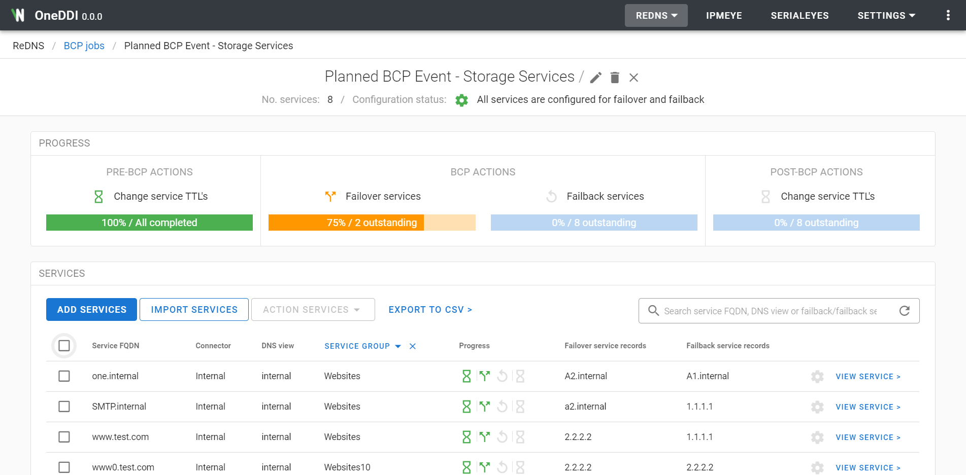
Detailed information about a BCP job, its configuration and its progress can be accessed by clicking the VIEW BCP JOB link displayed to the right of a BCP job under the ReDNS / BCP jobs page.
The View BCP job page is divided into multiple sections.
At the top of the View BCP job page the BCP jobs name, no. services associated to the BCP job, and the failover/failback configuration status of all associated services are displayed. Additionally, an edit BCP job and delete BCP job button is be displayed to the right of the BCP job name. If the currently authenticated user has NOT been assigned permission to manage BCP jobs the edit BCP job and delete BCP job button will be disabled.
The PROGRESS section displays the progress for each action which will be performed for the BCP job for all services. If the BCP job has been configured to include a pre/post BCP TTL change action the progress section is divided into four sections, one for the pre-BCP TTL change, one for failover, one for failback and one for post-BCP TTL change. Otherwise the progress section is divided into two sections, one for failover and one for failback. In both cases each section displays a progress indicator of which services have had the related action completed.
The SERVICES section displays a table containing the services added to the BCP job, along with the progress for each BCP action for each service.
The following columns are displayed in the table for each service:
For the progress column, if an action has not yet been completed it can be clicked to display the Mark action as completed dialog. See the ReDNS / BCP Jobs / Mark BCP Action as Complete section for more details on skipping an action by marking it as already completed.
A search control is displayed to the top right of the table. Values in the search field will be matched against the service FQDN, DNS view, failover service records and the failback service records fields.
Paging controls are displayed to the bottom right of the table. These can be used to page through the list of services, and to control how many are displayed in a single page.
The button ADD SERVICES will be displayed to the top left of the table. Upon clicking this button, the Add BCP job services dialog will be displayed. See the ReDNS / BCP Jobs / Add BCP Job Services section for details on this dialog and adding services to a BCP job.
Upon hovering over a row in the table a configure service for failover and failback button will be displayed to the right. If the currently authenticated user has NOT been assigned permission to manage services, or is not associated with a group that is specified in the services permissions, this button will be disabled. Either permission is required to configure the service for failover and failback for the BCP job. Upon clicking this button, the Configure service for BCP job dialog will be displayed. See the ReDNS / BCP Jobs / Configure a Service for Failover and Failback section for details on this dialog.
A checkbox is displayed to the left of each row in the services table. This can be used to select multiple services. Once at least one service is selected the ACTION SERVICES button displayed to the top of the table will be enabled. This menu contains actions to perform for BCP events, and to manage services. If the currently authenticated user has NOT been assigned permission to manage services, or is not associated with a group that is specified in the services permissions, the checkbox for the service will be disabled. Either permission is required to perform any of the actions under the ACTION SERVICES menu.
The DELETE SERVICES link under the MANAGE SERVICES section in the ACTION SERVICES menu can be used to delete services from the BCP job. Clicking this link will result in the Delete BCP job services dialog being displayed. See the ReDNS / BCP Jobs / Delete BCP Job Services section for details on this dialog.
The CHECK SERVICE HEALTH link under the MANAGE SERVICES section in the ACTION SERVICES menu can be used to check the health of services associated with the BCP job. Clicking this link will result in the Check service health dialog being displayed. See the ReDNS / BCP Jobs / Check Service Health section for details on this dialog.
The CHANGE SERVICE TTL’S link under the PRE-BCP ACTIONS section in the ACTION SERVICES menu can be used to change the TTL’s of one or more services, for example to reduce the TTL’s ahead of a planned BCP event. Clicking this link will result in the Change service TTL’s (pre-BCP) dialog being displayed. See the ReDNS / BCP Jobs / Change Service TTL’s (pre-BCP) section for details on this dialog. This link will be disabled if the failover action has been completed for one of the selected services already.
The FAILOVER SERVICES link under the BCP ACTIONS section in the ACTION SERVICES menu can be used to failover one or more services. Clicking this link will result in the Failover services dialog being displayed. See the ReDNS / BCP Jobs / Failover Services section for details on this dialog. This link will be disabled if the failover action has been completed for one of the selected services already.
The FAILBACK SERVICES link under the BCP ACTIONS section in the ACTION SERVICES menu can be used to failback one or more services. Clicking this link will result in the Failback services dialog being displayed. See the ReDNS / BCP Jobs / Failback Services section for details on this dialog. This link will be disabled if the failback action has been completed for one of the selected services already, or the failover action has not been completed for one of the selected services yet.
The CHANGE SERVICE TTL’S link under the POST-BCP ACTIONS_ section in the ACTION SERVICES menu can be used to change the TTL’s of one or more services, for example to increase the TTL’s following a planned BCP event. Clicking this link will result in the Change service TTL’s (post-BCP) dialog being displayed. See the ReDNS / BCP Jobs / Change Service TTL’s (post-BCP) section for details on this dialog. This link will be disabled if the failover action has not yet been completed for one of the selected services.
The link EXPORT TO CSV will be displayed to the top of the left of the table. Upon clicking this link all services assigned to the BCP job will be exported to a CSV file and downloaded. See the ReDNS / BCP Jobs / Export to CSV section for details on exporting services.
Services are added to a BCP job using the Add BCP job services dialog. This can be accessed by clicking the ADD SERVICES button displayed in the View BCP job page for a BCP job.
This dialog will display a table of available services. Available services are ones which are not currently associated with the BCP job, and services the currently authenticated user has permissions to swap (either the currently authenticated user is part of a group with permissions to manage services, or is associated with a group that is specified in the services permissions).
The following columns are displayed in the table:
A search control is displayed to the top of the table. Values in the search field will be matched against a services Service FQDN or DNS view. Additionally, services can be filtered by service group using the service group dropdown in the header of the service group column in the table.
Paging controls are displayed to the bottom right of the table. These can be used to page through the list of services, and to control how many are displayed in a single page.
A checkbox is displayed to the left of each service, the checkbox of the services which should be added to the BCP job should be checked, then the ADD button should be clicked, after which the services will be added to the BCP job.
Services are deleted from a BCP job by clicking the DELETE SERVICES link under the MANAGE SERVICES section of the ACTION SERVICES menu displayed in the SERVICES panel in the View BCP job page for a BCP job, once the services checkboxes have been checked. If the currently authenticated user has NOT been assigned permission to manage services, or is not associated with a group that is specified in the services permissions, the services checkbox will not be enabled. Either permission is required to perform health checks for a service using this feature.
The Delete BCP job services dialog will display a table of the services which are to be deleted from the BCP job. The following columns are displayed in the table:
Click the DELETE to delete the services from the BCP job, after which the services will be deleted from the BCP job.
Services are configured for failover and failback using the Configure service for BCP job dialog. This can be accessed by clicking the configure button displayed to the right when hovering over a service in the View BCP job page for a service. If the currently authenticated user has NOT been assigned permission to manage services, or is not associated with a group that is specified in the services permissions, this button will be disabled. Either permission is required to configure the service for failover and failback.
This dialog contains two tabs. The FAILOVER SERVICE RECORDS tab contains the service records which should be made active when the failover action is performed for the service. The EDIT SELECTED SERVICE RECORDS button can be used to add or remove service records from the list.
The FAILBACK SERVICE RECORDS tab contains the service records which should be made active when the failback action is performed for the service. The EDIT SELECTED SERVICE RECORDS button can be used to add or remove service records from the list.
Click the SAVE button to save changes to the failover and failback configuration.
Services can be imported to a BCP job using the Import BCP job services dialog. This can be accessed by clicking the IMPORT SERVICES button displayed in the View BCP Job page.
In this dialog a CSV import file must be specified which contains the services to be imported to the BCP job. The CSV import file should define one services per line using the following fields:
FQDN,Connector,DNS view,Service group,Failover service records,Failback service records
All fields are required, excluding the service group field which is included to be compatible with the BCP job service CSV export format, as follows:
If the CSV import file contains a header row as its first row, ensure the Select to skip the first row in the CSV import file if it contains headers field is selected to ignore the first row.
An example CSV import file can also be downloaded using the DOWNLOAD EXAMPLE CSV IMPORT FILE link which can be used as a starting point for a CSV import.
Once the CSV import file has been specified the VERIFY button can be clicked. A check will be performed to ensure the services and service records specified exist and that the services don’t already exist on the BCP job. If an issue is identified an error will be displayed.
Once successfully verified the IMPORT button can be clicked. Once clicked all services will be added to the BCP job.
The services associated with a BCP job are exported to CSV using the EXPORT TO CSV link displayed in the ReDNS / BCP jobs / View BCP job_ page. Upon clicking this link all services associated with the BCP job will be exported to a CSV file and downloaded, with the resulting CSV file having the following fields:
The health of multiple services can be changed using the Check search health dialog. This can be accessed by clicking the CHECK SERVICE HEALTH link under the MANAGE SERVICES section of the ACTION SERVICES menu displayed in the SERVICES panel in the View BCP job page for a BCP job, once the services checkbox has been checked. If the currently authenticated user has NOT been assigned permission to manage services, or is not associated with a group that is specified in the services permissions, the services checkbox will not be enabled. Either permission is required to perform health checks for a service using this feature.
During a service health check the underlying platform will be queried to understand the current state of a service. The service health check will attempt to identify issues which would prevent the successful swap of any of the configured service records for each service.
Click the START SERVICE HEALTH CHECK button to perform the health check.
A progress bar is displayed and updated as the health check progresses. As issues are identified they will be displayed. Once the health check is complete, if no errors were found the progress bar will be coloured green and indicate that no issues were found. Otherwise the progress bar will be coloured red and indicate at least one issue was found.
A table will be also be displayed listing all the services which will be checked, with the following columns:
Service FQDN - The services Fully Qualified Domain NameConnector - The connector the service is associated withDNS view - The DNS view the service is configured withStatus - If no issues were identified complete will be displayed,
otherwise failed with error: At least one issue has been detected! will be
displayed and an toggle expand icon will be displayed which once clicked
will display the errors identified for a serviceFor each issue found either an amber triangle or a red warning circle is displayed. Amber should be addressed, but they would not prevent the service from being successfully swapped. Red items are likely to prevent a service from being swapped successfully, and should be addressed.
Each issue identifies an issue with either one of the configured service records for a service, or the services Service FQDN itself. The exact item is displayed along with details of the issue. The following is an example issue:
In the above error an issue was identified with the service record which is
configured with the record type of a-record and the target IP address of
1.1.1.1.. The service record is marked as active in OneDDI, but when
consulting the underlying Infoblox platform no A record could be found for the
Service FQDN of svc1.vendorn.com which resolved to 1.1.1.1.
This issue would prevent a successful swap of the service and would have to be addressed.
Before the failover action is completed for one or more services the TTL’s for the services can be changed using the Change service TTL’s (pre-BCP) dialog. This can be accessed by clicking the CHANGE SERVICE TTL’S link under the PRE-BCP ACTIONS section of the ACTION SERVICES menu displayed in the SERVICES panel in the ReDNS / BCP Job / View BCP job page for a service, once the services checkboxes have been checked. If the currently authenticated user has NOT been assigned permission to manage services, or is not associated with a group that is specified in the services permissions, the services checkbox will not be enabled. Either permission is required to change service TTL’s.
The Change service TTL’s (pre-BCP) dialog displays a three step wizard which guides a user through specifying new TTL configuration, reviewing the changes which will be made, and then executing each change while displaying progress.
Upon entering the wizard step 1, the New TTL configuration page, is displayed.
This step can be used to specify the new TTL configuration. Two radio button
options are presented, one must be selected. The first Configure all services
to use the following TTL allows a TTL to be specified in seconds with
several pre-sets provided for quick selection. The second Remove the
existing TTL configuration and use the DNS zone default TTL results in the
existing TTL configuration being removed and the services inheriting the
DNS zone defaults TTL.
Once the new TTL configuration has been specified the NEXT button can be clicked to move on to step 2, the Review actions page. This page presents what changes will be made to the underlying platform to change service TTL’s. A table is displayed consisting of one row per service, with the following columns:
Service FQDN - The services Fully Qualified Domain NameConnector - The connector the service is associated withDNS view - The DNS view the service is configured withNew TTL - The TTL which the service will be reconfigured to use, e.g.
1 hour, hovering over this field will result in a tooltip being displayed
which shows the TTL in seconds, if the service is configured to use the DNS
zone default TTL this will be the string Use DNS zone defaultOnce the actions have been reviewed, the select field Select to continue if an error occurs processing an action can be selected to indicate if an error occurs processing a service it should not prevent the TTL changes from running to completion, an attempt will be made to change the TTL’s of all services in this case. Otherwise, if not selected, the TTL change will stop at the first error.
Once a comment has been entered in the required Comment field the CHANGE NOW button can be clicked after which step 3, the Process actions page will be displayed and the TTL change will start.
During the TTL change each action is processed and a progress bar updated. Once complete, if the TTL change was successful the progress bar will turn green and indicate the TTL change completed successfully. Otherwise the progress bar will turn red and indicate at least one error occurred.
A results table will also be displayed containing all the services actioned and the outcome. If an error occurred actioning a service the error will be displayed in the results table alongside the corresponding service.
Once the TTL change is complete click the CLOSE button to close the dialog.
The failover action can be completed for one or more services using the Failover services dialog. This can be accessed by clicking the FAILOVER SERVICES link under the BCP ACTIONS section of the ACTION SERVICES menu displayed in the SERVICES panel in the ReDNS / BCP Job / View BCP job page for a service, once the services checkboxes have been checked. If failover has already been completed for one of the selected services this link will be disabled. If the currently authenticated user has NOT been assigned permission to manage services, or is not associated with a group that is specified in the services permissions, the services checkbox will not be enabled. Either permission is required to failover services.
The Failover services dialog displays a two step wizard which allows a user to review the changes which will be made, and then executing each change while displaying progress.
Upon entering the wizard step 1, the Review actions page, is displayed. This page presents which services the failover action will be performed for. A table is displayed consisting of one row per service, with the following columns:
Service FQDN - The services Fully Qualified Domain NameConnector - The connector the service is associated withDNS view - The DNS view the service is configured withService group - The service group associated with the serviceOnce the actions have been reviewed, the select field Select to continue if an error occurs processing an action can be selected to indicate if an error occurs processing a service it should not prevent the failover from running to completion, an attempt will be made to failover all services in this case. Otherwise, if not selected, failover will stop at the first error.
Once a comment has been entered in the required Comment field the FAILOVER NOW button can be clicked after which step 2, the Process actions page will be displayed and failover will start.
During failover each action is processed and a progress bar updated. Once complete, if failover was successful the progress bar will turn green and indicate the failover completed successfully. Otherwise the progress bar will turn red and indicate at least one error occurred.
A results table will also be displayed containing all the services actioned and the outcome. If an error occurred actioning a service the error will be displayed in the results table alongside the corresponding service.
Once failover is complete click the CLOSE button to close the dialog.
The failback action can be completed for one or more services using the Failback services dialog. This can be accessed by clicking the FAILBACK SERVICES link under the BCP ACTIONS section of the ACTION SERVICES menu displayed in the SERVICES panel in the ReDNS / BCP Job / View BCP job page for a service, once the services checkboxes have been checked. If failover has NOT yet been completed for one of the selected services this link will be disabled. If the currently authenticated user has NOT been assigned permission to manage services, or is not associated with a group that is specified in the services permissions, the services checkbox will not be enabled. Either permission is required to failback services.
The Failback services dialog displays a two step wizard which allows a user to review the changes which will be made, and then executing each change while displaying progress.
Upon entering the wizard step 1, the Review actions page, is displayed. This page presents which services the failback action will be performed for. A table is displayed consisting of one row per service, with the following columns:
Service FQDN - The services Fully Qualified Domain NameConnector - The connector the service is associated withDNS view - The DNS view the service is configured withService group - The service group associated with the serviceOnce the actions have been reviewed, the select field Select to continue if an error occurs processing an action can be selected to indicate if an error occurs processing a service it should not prevent the failback from running to completion, an attempt will be made to failback all services in this case. Otherwise, if not selected, failback will stop at the first error.
Once a comment has been entered in the required Comment field the FAILBACK NOW button can be clicked after which step 2, the Process actions page will be displayed and failback will start.
During failback each action is processed and a progress bar updated. Once complete, if failback was successful the progress bar will turn green and indicate the failback completed successfully. Otherwise the progress bar will turn red and indicate at least one error occurred.
A results table will also be displayed containing all the services actioned and the outcome. If an error occurred actioning a service the error will be displayed in the results table alongside the corresponding service.
Once failback is complete click the CLOSE button to close the dialog.
Once the failover action has been completed for one or more services the TTL’s for the services can be changed using the Change service TTL’s (post-BCP) dialog. This can be accessed by clicking the CHANGE SERVICE TTL’S link under the POST-BCP ACTIONS section of the ACTION SERVICES menu displayed in the SERVICES panel in the ReDNS / BCP Job / View BCP job page for a service, once the services checkboxes have been checked. If the currently authenticated user has NOT been assigned permission to manage services, or is not associated with a group that is specified in the services permissions, the services checkbox will not be enabled. Either permission is required to change service TTL’s.
The Change service TTL’s (post-BCP) dialog displays a three step wizard which guides a user through specifying new TTL configuration, reviewing the changes which will be made, and then executing each change while displaying progress.
Upon entering the wizard step 1, the New TTL configuration page, is displayed. This step can be used to specify the new TTL configuration.
Before the new TTL configuration can be specified one of two radio buttons need
to be selected. The Revert service TTL's to their previous values where
possible can be selected to indicate that the TTL’s in use by each service
before they were changed using the change service TTL’s pre-BCP action should
be used. Otherwise, to specify that all services must use a specified TTL,
ignoring any TTL they may have been configured before failover, by selecting
the Ignore the previous TTL values for all selected services and use the TTL
configuration below. If none of the selected services have had their TTL’s
changed before failover, these two radio buttons will not be displayed.
Two radio button options are then presented to specify new TTL configuration,
one must be selected. The first Configure all services to use the following
TTL allows a TTL to be specified in seconds with several pre-sets provided for
quick selection. The second Remove the existing TTL configuration and use the
DNS zone default TTL results in the existing TTL configuration being removed
and the services inheriting the DNS zone defaults TTL.
Once the new TTL configuration has been specified the NEXT button can be clicked to move on to step 2, the Review actions page. This page presents what changes will be made to the underlying platform to change service TTL’s. A table is displayed consisting of one row per service, with the following columns:
Service FQDN - The services Fully Qualified Domain NameConnector - The connector the service is associated withDNS view - The DNS view the service is configured withNew TTL - The TTL which the service will be reconfigured to use, e.g.
1 hour, hovering over this field will result in a tooltip being displayed
which shows the TTL in seconds, if the service is configured to use the DNS
zone default TTL this will be the string Use DNS zone default, if it was
specified to use previous TTL’s if available in step 1, and the a previous
TTL is available, the TTL will be displayed along with (previous TTL),
i.e. an hour (previous TTL)Once the actions have been reviewed, the select field Select to continue if an error occurs processing an action can be selected to indicate if an error occurs processing a service it should not prevent the TTL changes from running to completion, an attempt will be made to change the TTL’s of all services in this case. Otherwise, if not selected, the TTL change will stop at the first error.
Once a comment has been entered in the required Comment field the CHANGE NOW button can be clicked after which step 3, the Process actions page will be displayed and the TTL change will start.
During the TTL change each action is processed and a progress bar updated. Once complete, if the TTL change was successful the progress bar will turn green and indicate the TTL change completed successfully. Otherwise the progress bar will turn red and indicate at least one error occurred.
A results table will also be displayed containing all the services actioned and the outcome. If an error occurred actioning a service the error will be displayed in the results table alongside the corresponding service.
Once the TTL change is complete click the CLOSE button to close the dialog.
A specific BCP action for a specific service can be skipped and mark as completed using the Mark action as completed dialog. This can be accessed by clicking the specific action icon displayed in the progress column for the service in the View BCP job page. If the currently authenticated user has NOT been assigned permission to manage services, or is not associated with a group that is specified in the services permissions, this button will be disabled. Either permission is required to mark BCP actions as complete for a service.
The mark complete dialog prompts whether the specified BCP action should be marked as completed for the service.
Click the APPLY button to confirm the specified BCP action should be marked as completed for the service, after which it will be marked as completed.
NOTE This is a destructive operation which cannot be undone.
BCP jobs can be reused. The current progress for a fully, or partially, completed BCP job can be reset using the Reset BCP job progress dialog. This can be accessed by clicking the reset BCP job progress button displayed to the right of a BCP job name at the top of the ReDNS / BCP Jobs / View BCP job page. If the currently authenticated user NOT been assigned permission to manage BCP jobs this button will be disabled.
The reset progress dialog prompts whether BCP job progress should be reset.
Click the RESET button to confirm BCP job progress should be reset, after which BCP job progress will be reset.
BCP jobs are edited using the Edit BCP job dialog. This can be accessed by clicking the edit BCP job button displayed to the right when hovering over a service in the ReDNS / BCP jobs page, or displayed to the right of a BCP job name at the top of the View BCP job page. If the currently authenticated user NOT been assigned permission to manage BCP jobs this button will be disabled.
This dialog contains the following inputs:
Click the SAVE button to save changes to the BCP.
NOTE This is a destructive operation which cannot be undone.
BCP jobs are deleted using the Delete BCP job dialog. This can be accessed by clicking the delete BCP job button displayed to the right when hovering over a BCP job in the ReDNS / BCP Jobs page, or displayed to the right of a BCP jobs name at the top of the ReDNS / BCP jobs / View BCP job page. If the currently authenticated user NOT been assigned permission to manage BCP jobs this button will be disabled.
The delete dialog prompts whether the BCP job should be deleted.
Click the DELETE button to confirm the BCP job should be deleted, after which the BCP job will be deleted.
Devices are viewed and managed under the IPMeye page by clicking the IPMeye link displayed in the top menu bar.
The IPMeye page will display a table of all defined devices.
The following columns are displayed in the table for each device:
ibdevice110.0.0.1623A search control is displayed to the top right of the table. Values in the search field will be matched against a devices name.
Paging controls are displayed to the bottom right of the table. These can be used to page through the list of devices, and to control how many are displayed in a single page.
The button ADD A DEVICE will be displayed to the top left of the table. If the currently authenticated user has NOT been assigned permission to manage devices this button will be disabled. Upon clicking this button, the Add a device dialog will be displayed. See the IPMeye / Add a Device section for details on this dialog and adding devices.
The button IMPORT DEVICES will be displayed to the top of the left of the table. If the currently authenticated user has NOT been assigned permission to manage devices this button will be disabled. Upon clicking this button, the Import devices dialog will be displayed. See the IPMeye / Import Devices section for details on this dialog and importing devices.
The link EXPORT TO CSV will be displayed to the top of the left of the table. Upon clicking this link, all devices will be exported to a CSV file and downloaded. See the IPMeye / Export to CSV section for details on exporting devices.
The link IPMI CONSOLE will be displayed to the right of each device. Upon clicking this link, the IPMI console page will be displayed for the device. See the IPMeye / IPMI Console section for details on this page and viewing a devices console.
If a SerialEyes module license is installed, the link SERIAL CONSOLE will be displayed to the right of each device. Upon clicking this link, the SerialEyes page will be displayed with the IP address and port fields populated from the device. See the SerialEyes / Connect to a Device section for details on this page.
Upon hovering over a row in the table an edit device and delete device button will be displayed to the right. If the currently authenticated user has NOT been assigned permission to manage devices these buttons will be disabled.
Upon clicking the edit device button the Edit device dialog will be displayed. See the IPMeye / Edit a Device section for details on this dialog and editing a device.
Upon clicking the delete device button the Delete device dialog will be displayed. See the IPMeye / Delete a Device section for details on this dialog and deleting a device.
Devices are added using the Add a device dialog. This can be accessed by clicking the ADD A DEVICE button displayed in the IPMeye page. If the currently authenticated user NOT been assigned permission to manage devices this button will be disabled.
This dialog contains the following inputs:
10.0.0.1623Once all required attributes have been specified the ADD button will be enabled, and once clicked the device will be added.
Devices are imported using the Import devices dialog. This can be accessed by clicking the IMPORT DEVICES button displayed in the IPMeye page. If the currently authenticated user NOT been assigned permission to manage devices this button will be disabled.
In this dialog a CSV import file must be specified which contains the devices to be imported. The CSV import file should define one device per line using the following fields:
Name,IP address,Port,IPMI username,IPMI password
The IPMI username and IPMI password fields are optional, and if not
specified users will be prompted for IPMI credentials when required. The Port
field is also optional, and if not specified the default IPMI port 623 will
be used.
If the CSV import file contains a header row as its first row, ensure the Select to skip the first row in the CSV import file if it contains headers field is selected to ignore the first row.
An example CSV import file can also be downloaded using the DOWNLOAD EXAMPLE CSV IMPORT FILE link which can be used as a starting point for a CSV import.
Once the CSV import file has been specified the VERIFY button can be clicked. A check will be performed to ensure an existing device using the same name or IP address does not already exist. If an existing device is found an error will be displayed.
Once successfully verified the IMPORT button can be clicked. Once clicked all devices will be added.
Devices are exported to CSV using the EXPORT TO CSV link displayed in the IPMeye page.
Upon clicking this link all devices are exported to CSV and downloaded, with the resulting CSV file having the following fields:
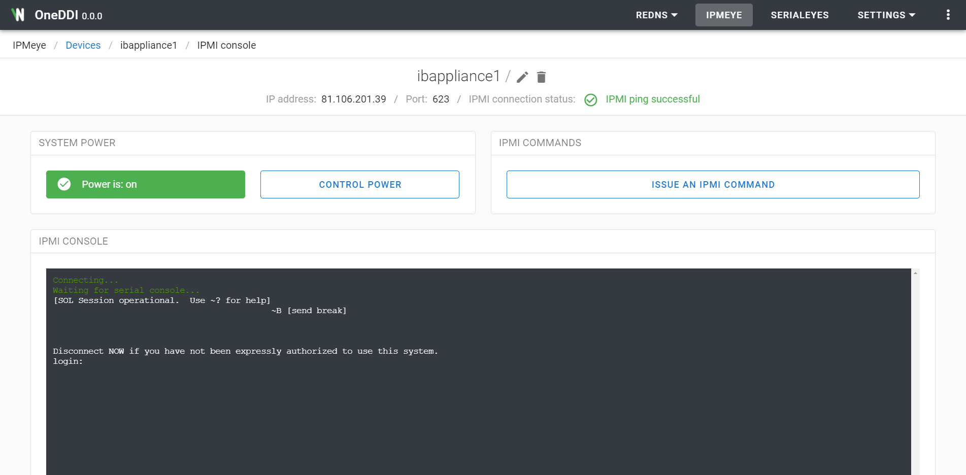
Name - Name of the device, i.e. device1.IP address - IP address used to connect to the device, i.e. 10.0.0.1.Port - IPMI port to use to connect to the device, i.e. 623.A devices IPMI console can be accessed by clicking the IPMI CONSOLE link displayed to the right of a device under the IPMeye page.
Devices can be pre-configured with IPMI credentials so that OneDDI users do not have to obtain and work with IPMI credentials. If a devices IPMI credentials have not been pre-configured the user will be prompted for an IPMI username and password each time the IPMI console page is navigated to.
The IPMI console page is divided into multiple sections.
At the top of the IPMI console page the devices name, IP address, port and its IPMI connection status is displayed. Additionally, an edit device and delete device button will be displayed to the right. If the currently authenticated user has NOT been assigned permission to manage devices these buttons will be disabled.
The SYSTEM POWER section displays the current power status. If system power this field is colour green, otherwise the field is coloured black. A CONTROL POWER button is displayed to the right of the power status. If the currently authenticated user has NOT been assigned permission to control device power this button will be disabled. Upon clicking this button, the Control power dialog will be displayed. See the IPMeye / Control Power section for details on this dialog and controlling device power.
The IPMI COMMANDS section displays the ISSUE AN IPMI COMMAND button. Upon clicking this button, the Issue an IPMI command dialog will be displayed. See the IPMeye / Issue an IPMI Command section for details on this dialog and issuing IPMI commands.
The IPMI CONSOLE section displays the devices serial console. Upon navigating to this page, and no user including the current user is connected to it already, an attempt will automatically be made to connect to the devices serial console. If a user including the current user is already connected to the devices serial console a message will be displayed indicating this, and no attempt will be made to connect to it.
Following a successful connect to the devices serial console the DISCONNECT button will be displayed to the bottom of the serial console. Upon clicking this button the current open connection will be closed.
When not connected to a devices serial console the CONNECT button will be displayed to the bottom of the serial console. Upon clicking this button an attempt will be made to connect to the devices serial console.
A circular download button is displayed to the bottom right of the console. When clicked the content currently displayed in the console will be exported to a text file and downloaded.
Serial console output is displayed in real-time, any text sent to the devices connected serial console will be displayed as it is read. To send input to the serial console, simply enter text as you would in a typical console. If the currently authenticated user has NOT been assigned permission to control the devices IPMI console the user will not be permitted to interact with the console, only view its output.
After a period of inactivity, the connection to the serial console will automatically be closed.
Device power can be controlled using the Control power dialog. This can be accessed by clicking the CONTROL POWER button displayed under the SYSTEM POWER section when viewing a devices console.
One of the following commands can be selected from the Power command input:
power-on - If system power is off it will be switched on.power-off - If system power is on it will be switched off - this will
result in a loss of power and the installed operating system will NOT be
given the opportunity to perform a so called “clean shutdown”.power-reset - If the system power is on a power-off style command will
first be issued. Next a power-on style command will be issued.acpi-shutdown - An ACPI event is issued to the installed operating system
after which the operating system should perform a so called “clean shutdown”.
This is different to a power-off command in that the system will maintain
power until the operating system has completed the shutdown.Once the desired power command is selected click the SEND COMMAND button, after which the selected command will be issued to the device. Following this it will take up to a minute for the system power to reflect the desired state.
Pre-determined IPMI commands can be issued using the Issue an IPMI command dialog. This can be accessed by clicking the ISSUE AN IPMI COMMAND button displayed under the IPMI COMMANDS section when viewing a devices console.
One of the following commands can be selected from the IPMI command input:
chassis-status - Display some physical state parameters, e.g. power fault
state, drive fault state and fan fault state.system-event-log-list - Display the Baseboard Management Controllers (BMCs)
system event log, this includes items such as power off/down events.sensor-list - Display all hardware sensors and their current values, e.g.
CPU temperature and fan speed.Once the desired IPMI command is selected click the SEND COMMAND button, after which the selected command will be issued to the device. The resulting output will be displayed in the dialog.
Devices are edited using the Edit a device dialog. This can be accessed by clicking the edit device button displayed to the right when hovering over a device in the IPMeye page, or displayed to the right of a devices IP address at the top of the IPMI console page. If the currently authenticated user NOT been assigned permission to manage devices this button will be disabled.
This dialog contains the following inputs:
10.0.0.1623Click the SAVE button to save changes to the device.
NOTE This is a destructive operation which cannot be undone.
Devices are deleted using the Delete a device dialog. This can be accessed by clicking the delete device button displayed to the right when hovering over a device in the IPMeye page, or displayed to the right of a devices IP address at the top of the IPMI console page. If the currently authenticated user NOT been assigned permission to manage devices this button will be disabled.
The delete dialog prompts whether the device should be deleted.
Click the DELETE button to confirm the device should be deleted, after which the device will be deleted.
Typically, a physical console server is used when connecting to a device’s physical serial port over the network. The console server would have a permanent physical connection to the device and a specific TCP port reserved such that protocols such as SSH or telnet would be used to connect to the physical console servers IP address using the device specific port. This would then provide access to the device’s physical serial port.
With SerialEyes no permanent physical console connection is required. Instead SerialEyes provides an on-demand connection by using a laptop, a bootable USB drive, and the OneDDI UI. The laptop acts as a secure conduit to OneDDI, allowing only specific users to connect to the devices serial port. A serial cable connects the laptop to a devices physical serial port, the laptop is booted from the USB drive which has the SerialEyes ISO image written to it, and then OneDDI is configured with the IP address and port that SerialEyes is now listening on.
When booting from the SerialEyes bootable USB drive the drive can contain a device specific SerialEyes configuration file which contains, among other items, the IP address on which it should listen for incoming connections. Alternatively, the parameters in the configuration file can be left unset. This will result in SerialEyes prompting for them on each boot. This allows a single USB drive to be used as a utility, along with a laptop, without having to plug the USB drive into another device to copy over a device specific configuration file each time SerialEyes is used.
The IP address used by SerialEyes can be any unused IP address, and is specified at connect time. For convenience, a devices existing IP address could be used, i.e. a management IP address, so long as the device is not using this IP address when SerialEyes is booted.
For example, for devices which support IPMI, the ethernet cable can be removed from the devices IPMI ethernet port and used along with the devices IPMI IP address and port. Once the device has been accessed and configured, the IPMI ethernet cable can be re-plugged back into the devices IPMI ethernet port. This provides seamless experience for deploying new devices, RMA and device re-initialisation scenarios.
SerialEyes uses a UDP port to listen for incoming connections, and by default uses UDP port 623, which is the default IPMI port. The IPMeye module in OneDDI will detect when a SerialEyes instance is using the IPMI IP address configured for a device in OneDDI and will display a status of “SerialEyes instance detected” under the IPMeye page.
To use SerialEyes two resources are required. One is an on-site engineer who has physical access to the device and will physically plug into the device’s physical serial port. The second is a OneDDI user who will access the devices physical serial port remotely using the SerialEyes features in OneDDI and will typically be someone with knowledge of the device and software it runs - i.e. the on-site engineer does not need any product specific knowledge for each device they are connecting SerialEyes to.
Connecting to a device using SerialEyes is accessed under the SerialEyes page by clicking the SerialEyes link displayed in the top menu bar.
When navigating to the SerialEyes page a three-step wizard is displayed which provides guidance on connecting SerialEyes to a device.
If a device was previously connected to and the page reloaded this page will be displayed again, in which case, simply enter the IP address, UDP port and connection key previously specified when creating a SerialEyes configuration file. Then click the VERIFY CONNECTIVITY button to view the devices serial port.
If the on-site engineer will enter SerialEyes configuration parameters when booting SerialEyes from the USB drive (e.g. IP address, UDP port, subnet mask, default gateway and connection key), there is no need to click the CREATE A SERIALEYES CONFIGURATION FILE button. In this case, simply enter the IP address, UDP port and connection key that will be used by SerialEyes.
Otherwise, click the CREATE A SERIALEYES CONFIGURATION FILE button after which the Create a SerialEyes Configuration File dialog will be displayed. In this dialog enter the parameters which will be used by SerialEyes when it is booted and click the CREATE AND DOWNLOAD button. Note that while a default connection key is suggested it is not required to use this key, and in fact the key can be anything the user wishes. However, it is advised that a different key be used each time SerialEyes is booted to improve security.
Next, an on-site engineer should be provided either a SerialEyes configuration file or the IP address, UDP and connection key specified in OneDDI. For the latter, the on-site engineer will also need to know the subnet mask and default gateway which SerialEyes should use on boot.
The on-site engineer should then follow the Connect SerialEyes Guide to use the SerialEyes configuration file, or parameters, to boot SerialEyes using the USB drive and laptop. This guide will identify how the on-site engineer can know that SerialEyes is booted and ready for connections.
Once the on-site engineer has confirmed SerialEyes is ready, click the VERIFY CONNECTIVITY button and after a successful check the SerialEyes / Serial Console page will be displayed.
The Serial console page is displayed following a successful connectivity check by clicking the VERIFY CONNECTIVITY button under the SerialEyes / Connect to Device page.
At the top of the Serial console page the IP address and UDP port used to connect to a device are displayed, along with the serial port connection status.
The SERIAL CONSOLE section displays the devices serial console. Upon navigating to this page, the CONNECT TO SERIAL PORT dialog will be displayed. The desired serial port and parameters should be selected and the CONNECT button clicked.
Following a successful connect to the specified serial port the DISCONNECT button will be displayed to the bottom of the serial console. Upon clicking this button, the serial port will be closed.
When not connected to a devices serial port the CONNECT TO SERIAL PORT button will be displayed to the bottom of the serial console again.
A circular download button is displayed to the bottom right of the console. When clicked the content currently displayed in the console will be exported to a text file and downloaded.
Serial console output is displayed in real-time, any text sent to the devices connected serial port will be displayed as it is read. To send input to the serial port, simply enter text as you would in a typical console. If the currently authenticated user has NOT been assigned permission to control the SerialEyes serial console the user will not be permitted to interact with the console, only view its output.
Users are viewed and managed under the Settings / Users page by clicking the Settings link displayed in the top menu bar and selecting the Users link displayed in the dropdown menu page.
If the currently authenticated user NOT been assigned permission to manage users they will not be permitted access to this page.
NOTE All users are equal, including the default admin user. User
permissions are determined based a user’s assigned groups, and the permissions
configured in all those groups.
The Settings / Users page will display a table of all defined users.
The following columns are displayed in the table for each user:
A search control is displayed to the top right of the table. Values in the search field will be matched against a user’s username.
Paging controls are displayed to the bottom right of the table. These can be used to page through the list of users, and to control how many are displayed in a single page.
The button ADD A USER will be displayed to the top left of the table. Upon clicking this button, the Add a user dialog will be displayed. See the Settings / Add a User section for details on this dialog and adding users.
Upon hovering over a row in the table an edit user and delete user button will be displayed to the right.
Upon clicking the edit user button, the Edit user dialog will be displayed. See the Settings / Users / Edit a User section for details on this dialog and editing a user.
Upon clicking the delete user button, the Delete user dialog will be displayed. See the Settings / Users / Delete a User section for details on this dialog and deleting a user.
Users are added using the Add a user dialog. This can be accessed by clicking the ADD A USER button displayed in the Settings / Users page.
This dialog contains several tabs. The USER tab contains the following inputs:
Below these inputs a GROUPS tab will be displayed where groups the user is associated with can be configured. The EDIT SELECTED GROUPS button can used change the current selection.
Once all required attributes have been specified the ADD button will be enabled, and once clicked the user will be added.
Users are edited using the Edit a user dialog. This can be accessed by clicking the edit user button displayed to the right when hovering over n user in the Settings / Users page.
This dialog contains several tabs. The USER tab contains the following inputs:
Below these inputs a GROUPS tab will be displayed where groups the user is associated with can be configured. The EDIT SELECTED GROUPS button can used change the current selection.
Click the SAVE button to save changes to the user.
NOTE This is a destructive operation which cannot be undone.
Users are deleted using the Delete a user dialog. This can be accessed by clicking the delete user button displayed to the right when hovering over a user in the Settings / Users page.
The delete dialog prompts whether the user should be deleted.
Click the DELETE button to confirm the user should be deleted, after which the user will be deleted.
Groups are viewed and managed under the Settings / Groups page by clicking the Settings link displayed in the top menu bar and selecting the Groups link displayed in the dropdown menu page.
If the currently authenticated user NOT been assigned permission to manage groups they will not be permitted access to this page.
The Settings / Groups page will display a table of all defined groups.
The following columns are displayed in the table for each group:
A search control is displayed to the top right of the table. Values in the search field will be matched against a group’s name.
Paging controls are displayed to the bottom right of the table. These can be used to page through the list of groups, and to control how many are displayed in a single page.
The button ADD A GROUP will be displayed to the top left of the table. Upon clicking this button, the Add a group dialog will be displayed. See the Settings / Add a Group section for details on this dialog and adding groups.
Upon hovering over a row in the table an edit group and delete group button will be displayed to the right.
Upon clicking the edit group button, the Edit group dialog will be displayed. See the Settings / Groups / Edit a Group section for details on this dialog and editing a group.
Upon clicking the delete group button, the Delete group dialog will be displayed. See the Settings / Groups / Delete a Group section for details on this dialog and deleting a group.
By default, a group is configured to permit read-only access to every module by using the following permission set:
view-ipmeyeview-rednsview-serialeyesThe following is a list of all the permissions which can be assigned to a group:
control-device-ipmi-console - Enable the use of the console in the IPMeye
modulecontrol-device-ipmi-power - Enable the control of devices power in the
IPMeye modulecontrol-serialeyes-console - Enable the use of the console in the
SerialEyes modulemanage-ad-authentication - Enable the management of Active Directory
authentication configuration in OneDDImanage-bcp-jobs - Enable the management of BCP jobs in OneDDImanage-connectors - Enable the management of Infoblox connectors in OneDDImanage-devices - Enable the management of devices in the IPMeye modulemanage-groups - Enable the management of groups in OneDDImanage-license - Enable license management in OneDDImanage-redundancy - Enable the management of replication and failover in
OneDDImanage-services - Enable the management of services in the ReDNS modulemanage-users - Enable the management of users in OneDDIview-ad-authentication - Enable read access to AD authentication
configuration in OneDDIview-audit-log - Enable read access to the audit log in OneDDIview-connectors - Enable read access to connector configuration in OneDDIview-groups - Enable read access to group configuration in OneDDIview-ipmeye - Enable read access to the IPMeye moduleview-license - Enable read access to license configuration in OneDDIview-redns - Enable read access to the ReDNS moduleview-redundancy - Enable read access to redundancy configuration in OneDDIview-serialeyes - Enable read access to the SerialEyes moduleview-users - Enable read access to user configuration in OneDDIGroups are added using the Add a group dialog. This can be accessed by clicking the ADD A GROUP button displayed in the Settings / Groups page.
This dialog contains several tabs. The GROUP tab contains the following inputs:
Using the PERMISSIONS tab, permissions which users associated with the group should inherit can be configured. The EDIT SELECTED PERMISSIONS button can used change the current selection. See the Settings / Groups / Available Permissions section to see what permissions are available.
Using the USERS tab, users which should be associated with the group can be configured. The EDIT SELECTED USERS button can used change the current selection.
Using the SERVICES tab, services which users associated with the group should be permitted to swap the active service records for can be configured. The EDIT SELECTED SERVICES button can used change the current selection.
Once all required attributes have been specified the ADD button will be enabled, and once clicked the group will be added.
Groups are edited using the Edit a group dialog. This can be accessed by clicking the edit group button displayed to the right when hovering over a group in the Settings / Groups page.
This dialog contains several tabs. The GROUP tab contains the following inputs:
Using the PERMISSIONS tab, permissions which users associated with the group should inherit can be configured. The EDIT SELECTED PERMISSIONS button can used change the current selection. See the Settings / Groups / Available Permissions section to see what permissions are available.
Using the USERS tab, users which should be associated with the group can be configured. The EDIT SELECTED USERS button can used change the current selection.
Using the SERVICES tab, services which users associated with the group should be permitted to swap the active service records for can be configured. The EDIT SELECTED SERVICES button can used change the current selection.
Click the SAVE button to save changes to the group.
NOTE This is a destructive operation which cannot be undone.
Groups are deleted using the Delete a group dialog. This can be accessed by clicking the delete group button displayed to the right when hovering over a group in the Settings / Groups page.
The delete dialog prompts whether the group should be deleted.
Click the DELETE button to confirm the group should be deleted, after which the group will be deleted.
Connectors are viewed and managed under the Settings / Connectors page by clicking the Settings link displayed in the top menu bar and selecting the Connectors link displayed in the dropdown menu page.
If the currently authenticated user NOT been assigned permission to manage connectors they will not be permitted access to this page.
The Settings / Connectors page will display a table of all defined Connectors.
Currently, Infoblox connectors are supported. An Infoblox connector manages the interaction with a single Infoblox Grid. Multiple Infoblox connectors can be created to interact with multiple Infoblox Grids.
The following columns are displayed in the table for each Connector:
gridMaster - IP address of the Grid Master to connect togridMasterCandidate - IP address of a candidate Grid Master which can be
used in the event the Grid Master is offlineport - HTTPS port used when connecting to the Grid Master or the Grid
Master candidateuseCandidate - Either true or false to indicate if the Grid Master
candidate is used when connecting to InfobloxA search control is displayed to the top right of the table. Values in the search field will be matched against an Connectors name or any of the key/value configuration items.
Paging controls are displayed to the bottom right of the table. These can be used to page through the list of Connectors, and to control how many are displayed in a single page.
The button ADD AN INFOBLOX CONNECTOR will be displayed to the top left of the table. Upon clicking this button, the Add Infoblox Connector dialog will be displayed. See the Settings / Connectors / Add an Infoblox Connector section for details on this dialog and adding Infoblox Connectors.
Upon hovering over a row in the table an edit Infoblox connector and delete Infoblox connector buttons will be displayed to the right.
Upon clicking the edit Infoblox connector button, the Edit Infoblox connector dialog will be displayed. See the Settings / Connectors / Edit an Infoblox Connector section for details on this dialog and editing an Infoblox Connector.
Upon clicking the delete Infoblox connector button, the Delete Infoblox connector dialog will be displayed. See the Settings / Connectors / Delete an Infoblox Connector section for details on this dialog and deleting an Infoblox connector.
Infoblox connectors are added using the Add an Infoblox connector dialog. This can be accessed by clicking the ADD AN INFOBLOX CONNECTOR button displayed in the Settings / Connectors page.
This dialog contains several tabs. The CONNECTOR tab contains the following inputs:
10.0.0.110.0.0.24432.10.Once all required attributes have been specified the TEST CONNECTIVITY button will be enabled, and once clicked the NIOS version for the Grid Master, and Grid Master Candidate if specified, will be fetched to verify the connection to each. The results from each check will be displayed.
The CREDENTIALS tab contains the following inputs:
NOTE The specified Infoblox user must have permission to read/write A records, CNAME records, Hosts and Aliases. Additionally, the user must also have permission to read/write all IPv4 networks (this permission is required to manage the previous object types using the Infoblox API).
Once all required attributes have been specified the ADD button will be enabled, and once clicked the Infoblox Connector will be added.
Infoblox connectors are edited using the Edit Infoblox connector dialog. This can be accessed by clicking the edit Infoblox connector button displayed to the right when hovering over an Infoblox connector in the Settings / Connectors page.
This dialog contains several tabs. The CONNECTOR tab contains the following inputs:
10.0.0.110.0.0.24432.10.Once all required attributes have been specified the TEST CONNECTIVITY button will be enabled, and once clicked the NIOS version for the Grid Master, and Grid Master Candidate if specified, will be fetched to verify the connection to each. The results from each check will be displayed.
The CREDENTIALS tab contains the following inputs:
Click the SAVE button to save changes to the Infoblox connector.
NOTE This is a destructive operation which cannot be undone.
Infoblox Connectors are deleted using the Delete Infoblox Connector dialog. This can be accessed by clicking the delete button displayed to the right when hovering over an Infoblox Connector in the Settings / Connectors page.
The delete dialog prompts whether the Infoblox Connector should be deleted.
Click the DELETE button to confirm the Infoblox Connector should be deleted, after which the Infoblox Connector will be deleted.
The Active Directory (AD) domains used for AD authentication are viewed and managed under the Settings / AD Authentication page by clicking the Settings link displayed in the top menu bar and selecting the AD Authentication link displayed in the dropdown menu page.
If the currently authenticated user NOT been assigned permission to manage AD authentication, they will not be permitted access to this page.
Once configured, a user from a configured AD domain can access the WebUI by
appending the domains DNS name to their username during authentication. For
example, the user stephen in the AD domain vendorn.com would specify
stephen@vendorn.com for their username at the OneDDI login page.
Following successful authentication, the users’ assigned AD groups will be matched with the names of the groups defined in OneDDI. If at least one group is not matched, then the user will not be permitted to access OneDDI - resulting in an invalid username/password type error.
Once authenticated, and the users’ groups discovered, the user will inherit the permissions from the matched OneDDI groups.
The Settings / AD Authentication page will display a table of all defined AD domains.
The following columns are displayed in the table for each user:
vendorn.com for the
username stephen@vendorn.com192.168.1.28 192.168.1.29:1234A search control is displayed to the top right of the table. Values in the search field will be matched against an AD domains DNS name.
Paging controls are displayed to the bottom right of the table. These can be used to page through the list of AD domains, and to control how many are displayed in a single page.
The button ADD AN AD DOMAIN will be displayed to the top left of the table. Upon clicking this button, the Add an AD domain dialog will be displayed. See the Settings / AD Authentication / Add an AD domain section for details on this dialog and adding AD domains.
Upon hovering over a row in the table an edit AD domain and delete AD domain button will be displayed to the right.
Upon clicking the edit AD domain button, the Edit AD domain dialog will be displayed. See the Settings / AD Authentication / Edit an AD domain section for details on this dialog and editing an AD domain.
Upon clicking the delete AD domain button, the Delete AD domain dialog will be displayed. See the Settings / AD Authentication / Delete an AD domain section for details on this dialog and deleting an AD domain.
AD domains are added using the Add an AD domain dialog. This can be accessed by clicking the ADD AN AD DOMAIN button displayed in the Settings / AD Authentication page.
This dialog contains the following inputs:
vendorn.com for the
username stephen@vendorn.com:<port> e.g.
ad1.internal or ad2.internal:636.Once all required attributes have been specified the TEST DOMAIN CONTROLLERS button will be enabled, and once clicked a TLS connection will be opened to each specified DC to verify the connection to each. The results from each check will be displayed.
Once all required attributes have been specified the ADD button will be enabled, and once clicked the AD domain will be added.
AD domains are edited using the Edit an AD Domain dialog. This can be accessed by clicking the edit AD domain button displayed to the right when hovering over an AD domain in the Settings / AD Authentication page.
This dialog contains the following inputs:
vendorn.com for the
username stephen@vendorn.com:<port> e.g.
ad1.internal or ad2.internal:636.Once all required attributes have been specified the TEST DOMAIN CONTROLLERS button will be enabled, and once clicked a TLS connection will be opened to each specified DC to verify the connection to each. The results from each check will be displayed.
Click the SAVE button to save changes to the AD domain.
NOTE This is a destructive operation which cannot be undone.
AD domains are deleted using the Delete an AD Domain dialog. This can be accessed by clicking the delete AD domain button displayed to the right when hovering over an AD domain in the Settings / AD Authentication page.
The delete dialog prompts whether the AD domain should be deleted.
Click the DELETE button to confirm the AD domain should be deleted, after which the AD domain will be deleted.
Two OneDDI instances are required to form a replication pair. One instance is active and replicates changes to the other standby instance. Once configured a standby instance will connect to its configured peer, the active instance, to receive and apply replication changes to its database.
The entire contents of the OneDDI database is replicated. The following items, not in this database, are not replicated since they are specific to a OneDDI instance:
/opt/oneddi/config
directory on the OneDDI serverReplication utilises the HTTPS connection already provided by the OneDDI server. The standby peer will connect to the active peer and wait for replication changes, i.e. the connection will remain open and ready for further replication changes.
All changes, regardless of whether the standby peer is connected to the active peer or not, are queued for replication. If the standby peer is connected, the change is immediately sent to it and removed from the replication change queue. If the standby is not connected, replication changes will remain in the replication queue until the standby next connects to the active peer, after which it will request and process all changes in the replication queue.
Replication configuration is stored in the /opt/oneddi/config/replication.json
file on the OneDDI server. On both the active and standby instances this file
includes the following:
An encrypted connection key is also found in this file. This key is used by both the active and standby peers to authenticate their communication. This key is sensitive and should not be transferred off the hosts in any way, or even copied out of this file.
In addition to using the connection key to authenticate communication, the peer
IP address configured in the above file is used to implement an IP access
control list for all replication communication to an instance. Any connections
not from the peer IP address configured, or the loopback address 127.0.0.1,
will be automatically closed and rejected.
There are two methods by which replication can be managed. If the active peer is available, the Settings / Redundancy page in the WebUI of the active peer can be used to perform the following:
If the active peer is not available and replication needs to be failed over to the standby peer, or replication must be deconfigured on the standby peer, the replication command must be used. The replication command and its usage are provided under the Redundancy / Replication section in the Admin Guide.
Replication is managed under the Settings / Redundancy page by clicking the Settings link displayed in the top menu bar and selecting the Redundancy link displayed in the dropdown menu page.
If the currently authenticated user NOT been assigned permission to manage redundancy, they will not be permitted access to this page.
If replication has not been configured the button CONFIGURE REPLICATION will be displayed. Upon clicking this button, the Configure replication dialog will be displayed. See the Settings / Redundancy / Configure Replication section for details on configuring replication.
If replication has been configured several sections of information will be displayed to show replication configuration status and health.
The Replication status section will identify the IP address of the active and standby peers. The FAILOVER TO STANDBY PEER button will be displayed underneath this information. If the standby peer is not connected to the active peer this button will be disabled. Upon clicking this button, the Failover to standby peer dialog will be displayed. See the Settings / Redundancy / Failover to Standby Peer section for details on failing over to the standby peer. The DECONFIGURE REPLICATION button will also be displayed. Upon clicking this button, the Deconfigure Replication dialog will be displayed. See the Settings / Redundancy / Deconfigure Replication section for details on deconfiguring replication.
The Replication health section displays the following indicators relating to the health of replication:
The SYNCHRONISE STANDBY PEER DATABASE button will be displayed underneath this information. If the standby peer is not connected to the active peer this button will be disabled. Upon clicking this button, the Synchronise standby peer database dialog will be displayed. See the Settings / Redundancy / Synchronise Standby Peer Database section for details on synchronising the standby peer database.
Real-time replication to another OneDDI instance can be performed using the Configure replication dialog which is accessed by clicking the CONFIGURE REPLICATION button displayed in the Settings / Redundancy page. If replication is already configured this button will not be accessible.
Two OneDDI instances are required to form a replication pair. One instance will be active and will replicate changes to the other standby peer. Both instances should be up and accessible and both should have their OneDDI product licenses installed.
The following actions will be taken to configure replication:
Once configured the standby instance will connect to the active instance to receive replication changes.
The Configure replication dialog displays a five step wizard which guides a user through configuring the active and standby peers, verifying replication can be configured on both, and then executing the required changes to configure replication on both the active and standby peers.
Step 1 in the dialog, the Start page, provides a brief overview of what will be performed to configure replication.
Click the NEXT button to continue to step 2, the Standby peer page. In this page the IP address and HTTPS port of the standby peer must be entered. The IP address can be any configured on the standby peer and the HTTPS port must be the port the WebUI is accessible via. Additionally, once configured, when users access the standby peer they will be redirected to the active peer using the IP address and HTTPS port of the active peer which will be entered in the next step of the wizard. This can be overridden by entering a URL in the Standby redirect URL field.
Click the NEXT button to continue to step 3, the Active peer page. In this page the IP address and HTTPS port of the active peer must be entered. These parameters are used to configure the IP address and HTTPS port the standby peer should use to connect to the active peer. The IP address can be any configured IP address on the active peer and the HTTPS port must be port the WebUI is accessible via. By default, the IP address and port the WebUI is currently being access through will be suggested. Additionally, once configured, when users access the active peer after a failover to the standby peer is performed (mean it is now the standby peer) they will be redirected to the active peer using the IP address and HTTPS port of the standby peer configured in the previous step of the wizard. This can be overridden by entering a URL in the Standby redirect URL field.
Click the NEXT button to continue to step 4, the Verify page. In this page
the username and password for a user which currently exists on the standby peer
must be entered. The specified user must be associated with a group which has
the manage-redundancy permission assigned. The user will be used to verify
replication can be configured, that connectivity between the active and
standby peers is working (in both directions), and once APPLY NOW is clicked,
it will also be used to configure replication on the standby peer. Click the
VERIFY CONFIGURATION button to contact to the standby peer and verify
replication can be configured. Any errors discovered during verification will
be displayed. Once verification is successful the APPLY NOW button will be
enabled.
Click the APPLY NOW button to configure replication on both the active and standby peers. After replication has been configured the Configure replication dialog will then be closed.
If replication has been configured, failover to a standby peer can be performed using the Failover to standby peer dialog which is accessed by clicking the FAILOVER TO STANDBY PEER button displayed in the Settings / Redundancy page. If the standby peer is not connected to the active peer this button will be disabled.
If failover to a standby peer must be performed when the active peer is not available, i.e. during a disaster recovery scenario, the replication command must be used since the WebUI cannot be accessed on standby instances. In this case refer to the Redundancy / Replication section in the Admin Guide.
The following actions will be taken to failover to the standby peer:
Once failover is complete all WebUI sessions will be destroyed and all users will be redirected to the newly active instance.
To failover to the standby peer simply click the FAILOVER button. Once failover is complete the WebUI is redirected to the newly active peer.
Replication can be deconfigured using the Deconfigure replication dialog which is accessed by clicking the DECONFIGURE REPLICATION button displayed in the Settings / Redundancy page.
If the peer which needs to be deconfigured is the standby peer, the replication command must be used since the WebUI cannot be accessed on standby instances. In this case refer to the Redundancy / Replication section in the Admin Guide.
The following actions will be taken to deconfigure replication:
If the standby peer is connected to the active peer the Select to also deconfigure replication on the standby peer select will be enabled and selected by default, otherwise it is disabled and unselected. If selected, then replication will also be deconfigured on the standby peer.
Once deconfigured both active and standby peers will be standalone instances and have their own independent copy of the current database.
To deconfigure replication simply click the DECONFIGURE button. Once deconfigured the Deconfigure replication dialog will then be closed.
If replication has been configured, the database for a standby peer can be synchronised on demand using the Synchronise standby peer database dialog which is accessed by clicking the SYNCHRONISE STANDBY PEER DATABASE button displayed in the Settings / Redundancy page. If the standby peer is not connected to the active peer this button will be disabled.
Under exceptional circumstances the standby peer database may become out-of-sync with the active peer database. In this case the standby peer can no longer accept replication changes from the active peer, and a message will be displayed under the Replication health section in the Settings / Redundancy page indicating an attempt to apply a change failed. Synchronising the standby peer’s database essentially overwrite the standby peer database with a copy of the database from the active peer, essentially removing any issues being reported at that point.
To synchronise the peer database simply click the SYNCHRONISE button. The standby peer database will then be synchronised, and once complete, the Synchronise standby peer database will then be closed.
The product license can be viewed under the Settings / License page by clicking the Settings link displayed in the top menu bar and selecting the License link displayed in the dropdown menu page.
If the currently authenticated user NOT been assigned permission to manage the product license, they will not be permitted access to this page.
A product license has several attributes which specify for example when it was created and to which customer it was issued. Along with these attributes, each license will contain a list of modules which are licensed. Each licensed module has its own valid from and valid to date. This allows customers to evaluate new product modules on their existing installation without it affecting their existing modules.
A complete new license will be issued to add new modules, i.e. only a single license is ever installed with the licensed modules specified by that single license, and this will include any modules being evaluated.
Product licenses are bound to an IP address. When validating a license, the licensed IP address will be checked against the locally configured IP addresses and if one is not matched the license will be considered invalid.
If a valid product license has been applied the customer to which the license has been issued will be displayed at the top of the page.
Below the customer name, the following license attributes will be displayed:
c1055315-bb04-4bca-a507-97414e7c8fec2020-02-01T00:00:00Z / a month ago192.168.1.12Below the license attributes a list of licensed modules will be displayed in a table. The following columns will be displayed for each licensed module:
ipmeye2020-02-01T00:00:00Z / a month ago2020-03-31T23:59:59Z / in a monthValid will be displayed, if the license has not yet expired,
but the Valid to field falls within the next 7 days from the current date
and time, an amber exclamation icon and the text Expires soon will be
displayed, and if the license has expired a red exclamation icon and the
text Expired will be displayedThe button APPLY A LICENSE will be displayed to the bottom of the license detail. Upon clicking this button, the Apply a license dialog will be displayed. See the Settings / Apply a License section for details on this dialog and applying a license.
A product license can be applied using the Apply a license dialog. This can be accessed by clicking the APPLY A LICENSE button displayed in the Settings / Product License page.
This dialog contains the following inputs:
Once all required attributes have been specified click the VERIFY button, after which the license will be verified.
Following successful license verification, the APPLY button will be enabled. Clicking the APPLY button will apply the license and replace the existing product license.
The application audit log can be viewed under the Settings / Audit log page by clicking the Settings link displayed in the top menu bar and selecting the Audit log link displayed in the dropdown menu page.
If the currently authenticated user NOT been assigned permission to view the audit log, they will not be permitted access to this page.
All actions performed in the OneDDI WebUI which create side-effects are audited. Audit events are created in the application audit log. In addition, all audit events are recorded to the system log file. Each message uses the following format:
AuditEntry: timestamp=<timestamp> username=<username> action=<action> detail=<json-detail>
The following is an example audit event logged to the system log:
AuditEntry: timestamp=2020-04-01T20:37:29Z username=stephen action=ConnectDeviceIpmiConsole detail={"id":"953727ab-a2d9-4c11-9370-fb64429a860c","name":"ibdevice1","ipAddress":"86.15.69.51","port":623}
The Settings / Audit log page will display a table of audit events.
The following columns are displayed in the table for each event:
ConnectDeviceIpmiConsole
or AddDeviceA search control is displayed to the top right of the table. Values in the search field will be matched against the username, action, or detail fields.
Paging controls are displayed to the bottom right of the table. These can be used to page through the list of events, and to control how many are displayed in a single page.